
From One Video Clip to an Articulated 3D Model
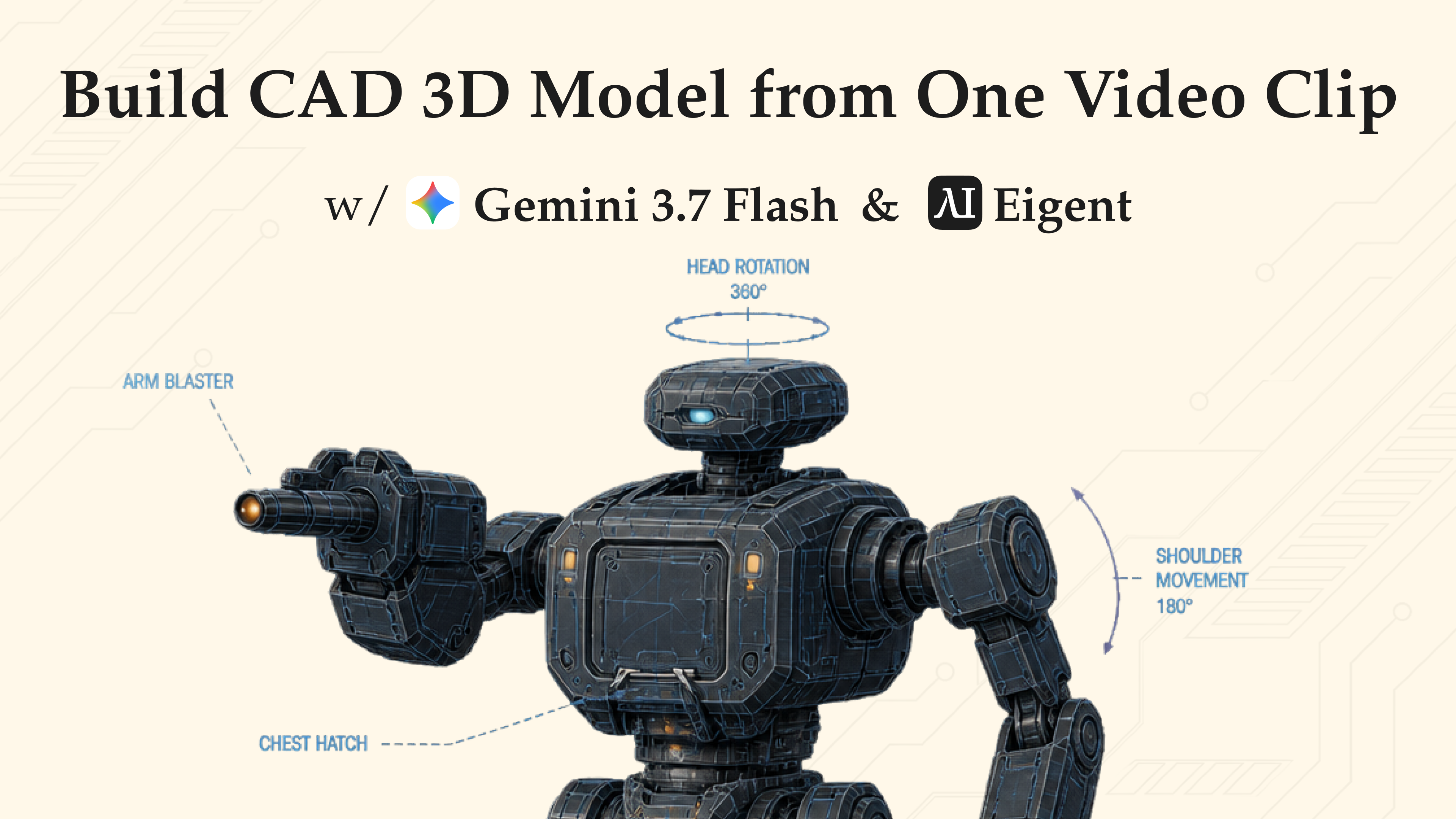
Building a mechanical character normally starts with a reference sheet: front, side, and rear views; close-ups of the joints; material callouts; and measured proportions. In this workflow, we gave Eigent just one reference video and asked Gemini 3.7 Flash to turn what it could observe into a detailed, articulated 3D mesh exported as a .glb file.
We then placed the result beside a Gemini 3.6 Flash run of the same task. In the recorded comparison, Gemini 3.7 Flash completed the task much faster and generated a more mechanically layered model, while the 3.6 Flash result used a simpler, blockier interpretation.
Here is how to reproduce the workflow.
Prepare the Reference Video
Choose a clip that makes the character easy to inspect. A useful input should:
- Keep the full character visible for as much of the clip as possible.
- Show multiple angles, especially the front, side, and back.
- Include clear views of the shoulders, elbows, hips, knees, ankles, and spine.
- Avoid excessive motion blur, hard cuts, and objects blocking the character.
- Preserve the original resolution instead of sending a compressed social-media copy.
One clip can be enough for a convincing concept mesh, but the model must infer any surfaces the camera never sees. For higher geometric fidelity, use a slow turntable-style video or provide additional reference images with the clip.
Add Gemini 3.7 Flash to Eigent
In Eigent, open Settings → Agents → Models → Gemini. Enter your Gemini API key, configure the API host if required by your provider, and set the model type to Gemini 3.7 Flash. Save the configuration, then select that custom model for the task.
The demo uses Eigent's single-agent workspace. This keeps the video analysis, modeling plan, file generation, and final response in one continuous context.
Start a Single-Agent Task and Upload the Clip
Create a new task in Cowork with Single Agent, attach the reference video, and confirm that the file appears with the message before sending it. The video is the source of truth for the character's silhouette, mechanical structure, colors, and visible articulation.
Paste the Full Modeling Prompt
Use the following prompt:
Analyze the transformers character in the uploaded reference video and generate a production-ready, highly detailed 3D CAD/mesh model exported as a .glb file.
1. Video Analysis & Reference Extraction
Character Identity & Style: Identify the Transformer's key design elements from the video, including mech proportion, silhouette, armor plating, color scheme, and mechanical aesthetics.
Joints & Articulation: Carefully analyze the body structure and joints, including shoulder ball joints, elbow hinges, hip sockets, knee hydraulics, spine segments, and ankle pivots. Ensure every joint is distinctly articulated and functional.
Surface Details: Capture intricate mechanical details including panel lines, exposed wiring, hydraulic pistons, glowing energy cores and lights, and mechanical greebles.
2. 3D Modeling & CAD Specifications
Detail Level: Ultra-high precision, hard-surface mechanical geometry. Use Sub-D or sharp-edge mechanical CAD styling.
Articulated Rigging Prep: Separate distinct body parts and armor pieces logically around joint pivot points so the model can be rigged or transformed later.
Visual Style: Cinematic, futuristic, and badass. Use high-contrast mechanical layering with subtle wear and scratch textures.
3. Material & Shading (PBR)
Use metallic PBR materials: anodized metals, brushed steel, dark titanium, and high-gloss armor-painted surfaces. Add emissive channels for the eyes, chest core, and joint glow effects.
4. Output Requirement
Format: GLB (.glb). Ensure all textures—Diffuse, Normal, Roughness, Metallic, and Emissive—are packed directly into the GLB.
Mesh integrity: Clean topology, manifold geometry, optimized for real-time preview without losing mechanical sharpness.
The prompt does three important things: it tells the model what to inspect, how the mesh should be organized, and how the final deliverable must be packaged. Without those constraints, a model may produce a visually plausible robot that is difficult to rig, edit, or preview elsewhere.
Let Gemini Analyze and Build
After the task starts, Gemini 3.7 Flash first interprets the video as a modeling reference. It identifies the visible silhouette, armor blocks, joint locations, color regions, and surface features, then converts that analysis into a 3D construction plan.
The requested output is a self-contained GLB, so geometry and PBR material data can travel together in one file. This makes the result easy to open in a browser-based GLB viewer or import into tools such as Blender for closer inspection.
Inspect the Gemini 3.7 Flash Result
Open the generated .glb in a 3D viewer and rotate it through every axis. In the demo, the Gemini 3.7 Flash result shows a recognizable humanoid mech with:
- A segmented head, torso, arms, and legs.
- More visible mechanical layering around the shoulders and limbs.
- Multiple color and material regions instead of one uniform shell.
- Distinct components that make the articulation structure easier to read.
- A more detailed overall silhouette than the 3.6 Flash output shown beside it.
Do not judge the model from the front view alone. Use the viewer's orbit, pan, and zoom controls to inspect the sides, back, gaps between armor plates, and the alignment of the major joint pivots.
Compare Gemini 3.7 Flash with 3.6 Flash
The final section of the demo plays both outputs side by side under the same CAD task.
| Comparison point | Gemini 3.7 Flash | Gemini 3.6 Flash |
|---|---|---|
| Completion speed | Much faster in this recorded run | Slower in this recorded run |
| Mechanical detail | More layered components and surface variation | Simpler, more block-like construction |
| Articulation readability | Limb and body segments are easier to distinguish | Major body parts are present but less granular |
| Visual richness | More color accents and small mechanical forms | Cleaner but more minimal interpretation |
This is a demonstration, not a controlled benchmark. Runtime can change with the clip, prompt, provider load, tool path, and output complexity. The useful conclusion is narrower: for this exact video-to-GLB task, the 3.7 Flash run was faster and produced the more detailed visual result.
Validate the GLB Before Production Use
"Production-ready" should be treated as an acceptance checklist, not an automatic property of an AI-generated file. Before rigging, animation, real-time deployment, or fabrication, verify:
- Topology: Look for non-manifold edges, duplicate faces, internal geometry, holes, and self-intersections.
- Transforms and scale: Confirm a sensible real-world scale, origin, forward axis, and applied transforms.
- Part separation: Make sure armor and body components are divided at useful joint boundaries rather than split arbitrarily.
- Joint pivots and clearance: Test shoulder, elbow, wrist, hip, knee, ankle, neck, and waist movement for collisions.
- Materials: Confirm that base color, normal, metallic, roughness, and emissive maps are embedded and connected correctly.
- Real-time performance: Measure triangle count, texture resolution, draw calls, and file size for the target platform.
- Reference fidelity: Compare the model with frames from every available camera angle, paying particular attention to inferred or unseen surfaces.
GLB is a mesh delivery format, not a parametric engineering CAD format. If the asset will be manufactured or must meet dimensional tolerances, rebuild or validate it in an appropriate CAD workflow rather than relying on the generated mesh alone.
Improve the Next Run
For a stronger second pass, ask Eigent to generate a validation report alongside the GLB:
Re-open the generated GLB and audit it against the original video. Report the triangle count, object hierarchy, material channels, non-manifold geometry, missing textures, joint pivot locations, and any visible differences from the reference. Fix critical issues and export a validated second version.
You can also request a lower-poly real-time version, a rig-ready hierarchy with a named bone map, or separate high- and low-detail LODs. That turns the first AI-generated mesh into the start of a practical 3D asset pipeline instead of treating it as the finished endpoint.